English
 简体中文
简体中文
 RU
RU
 PT
PT

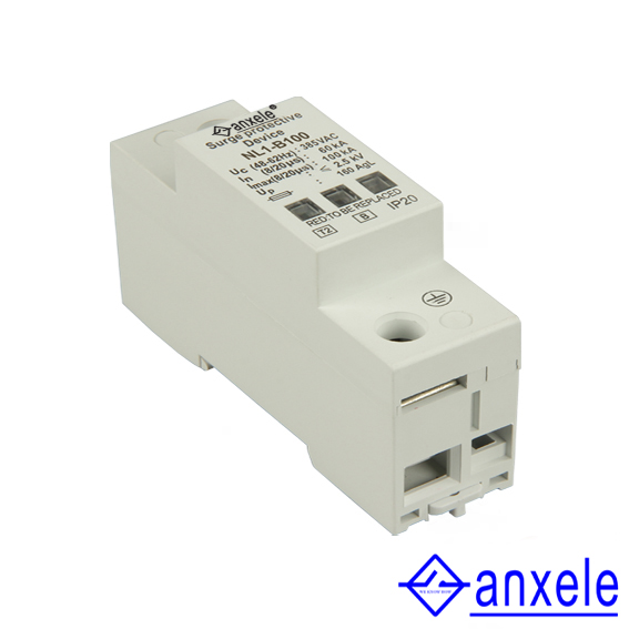
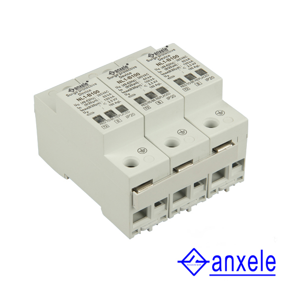
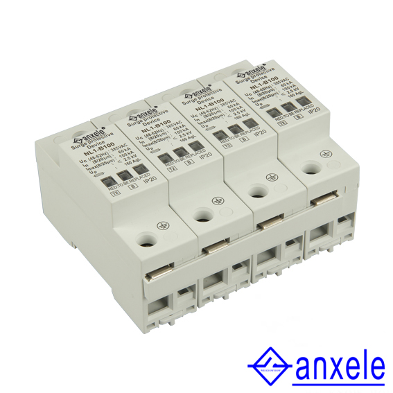
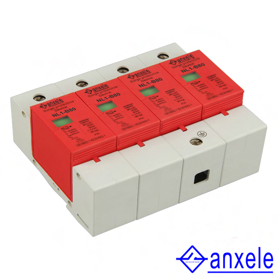
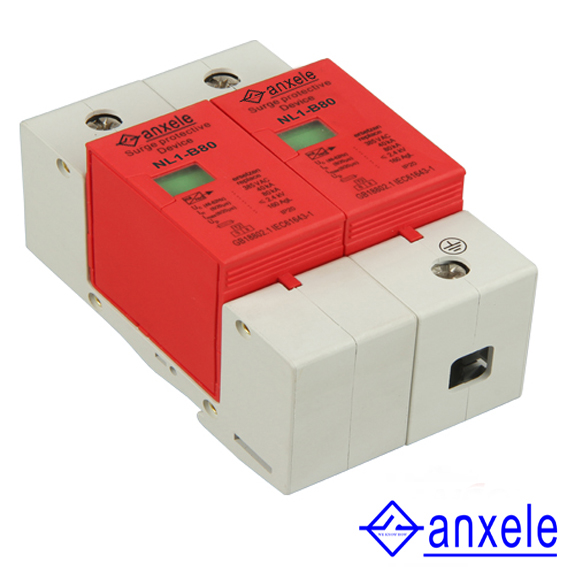
NL1-B100 1P Surge Protection Device
Spark Gap Surge Arrester
(B+C Combined Arrester )
NL1-B series surge protective device(in short: SPD, alias:surge protector, surge arrester)is suitable for TN-S. TN-C-S. TT. IT etc.power supply system of AC 50/60Hz.≤380V,and used at the equipotential connection,which protects the electric network not shocked by the thunder and lightning, it’s designed according to GB18802.1. IEC61643-1,it adopts 35mm standard rail,there is a failure release mounted on the module of surge protective device.When the SPD fails in breakdown for over-heat and over-current,the failure release will help electric device separate from the power system and green meas normal,red means abnormal,Kevin wiring mode,remote-signaling output interface.it’s also could be replaced for the module when has operating voltage.
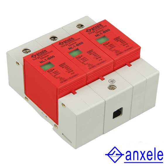
NL1-150. NL1-120. NL1-100 series surge Protective devices are suitable for B grade surge potection, used at the equipotential connection of LPZOA or LPZOB and LPZ1 zone,which protects the electrle network not shocked by the thunder.NL1-80. NL12-60series surge protec tive devices are usually installed in low voltage main distri bution box connected to the incoming end of the buildings.
Notice:When you order our goods,please write the model and quantity carefully.For example:NL1-B150/4-385,8 pieces.
Technical Parameters
| Technical Parameters | Model | NL1-B150 | NL1-B120 | NL1-B100 | NL1-B80 | NL1-B60 |
| Rated Operating Voltage Un(V~) | 220V,380V | 220V,380V | 220V,380V | 220V,380V | 220V,380V | |
| Maximum Continuous Operating Voltage Un(V~) | 385V,420V | 385V,420V | 385V,420V | 385V,420V | 385V,420V | |
| Voltage Protection Level Up(V~)kV | ≤4.0,≤4.5 | ≤3.4,≤3.7 | ≤2.8,≤3.2 | ≤2.4 | ≤1.8,≤2.2 | |
| Maximum Discharge Current Imax(8/20μs)kA | 150 | 120 | 100 | 80 | 60 | |
| Nominal Discharge Current In(8/20μs)kA | 100 | 80 | 60 | 40 | 30 | |
| Response Time ns | <100 | <25 | ||||
| L/N(mm2) The Cross Section of L/N Line | 25. 35 | 16. 25 | 16. 25 | 16. 25 | 16. 25 | |
| PE(mm2) The Cross Section of PE Line | 35 | 25. 35 | 25. 35 | 25. 35 | 16. 25 | |
| Fuse or Switch(A) | 63A. 125A | 63A. 100A | 63A. 100A | 63A | 63A | |
| (mm2) The Line Section of Communication and Alarm | ≥1.5 | |||||
| Operating Environment℃ | -40℃~+85℃ | |||||
| Relative Humidity(25℃) | ≤95% | |||||
| Installation | Standard Rail 35mm | |||||
| Material of Outer Covering | Fiber glass reinforced plastic | |||||